汇川伺服接线汇总,超详细!
点击数:18662 更新时间:11/10/2023 2:09:53 PM Tag:
汇川伺服接线 
由此可以看出ISMH1-10B30CB-U130X的参数为:低惯量、小容量,100W,额定转速3000rpm,电压等级220V,2500线省线式增量编码器,实心、带键、带螺纹孔,没有制动器、减速机、油封,自然冷却。
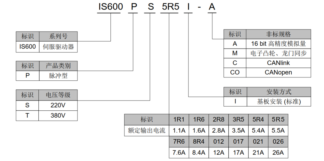
由此可以看出IS600PS1R1I-C参数为:脉冲型,电压等级220V,额定输出电流1.1A,基板安装,CANlink。3)主回路接线,L1C、L1和L2C、L2之间接220V交流电源,不接制动电阻时P+和D短接,接制动电阻时断开P+和D,再将电阻接在P+和C之间,U、V、W通过配套的专用电缆连接到电机主线,CN2通过配套的专用电缆连接到电机编码器。

4)伺服驱动器各接口端子内部引脚分布情况,特别时CN1接口。

5)伺服驱动器如何与1200 PLC连接,伺服通常有速度控制模式,位置控制模式和转矩控制模式三种,各自连接配线如下图所示,使用最多的是位置控制模式。

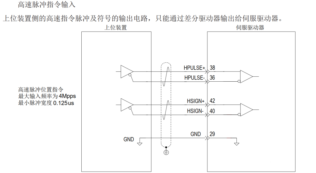
伺服驱动器位置控制支持两种脉冲指令输入,一是低速脉冲位置指令输入方式,二是高速脉冲位置指令输入。如下表所示:
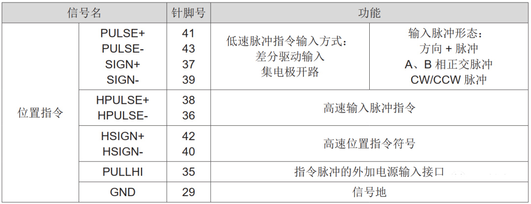
低速脉冲指令输入与不同输出类型的上位机装载连接方式不同,如

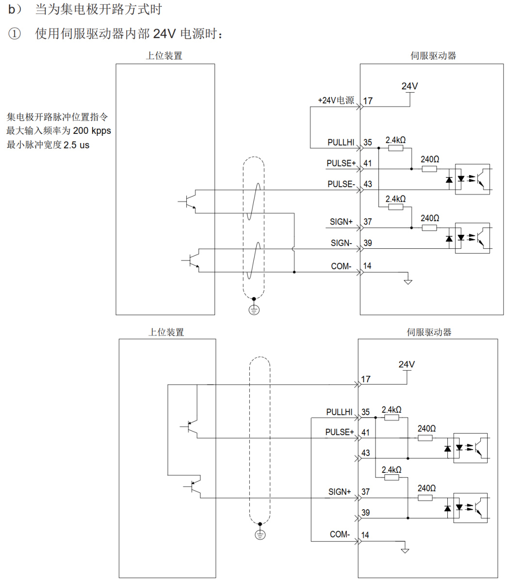
由于PLC常见信号为DC24V电压等级,使用内部电阻方案接线比较方便,当PLC输出脉冲信号为漏型0V时,采用下图接线方式。脉冲接PULSE-,方向接SIGN-,电压正极接PULLHI,PULSE+和SIGN+空置。也就是常说的工阳接法,三菱,信捷等品牌采用此接法。

西门子PLC输出为源型24V+,所以脉冲接PULSE+,方向接SIGN+,PULLHI接电源负极,PULSE-和SIGN-空置,这就是常说的共阴接法。所以1200PLC采用此接法。脉冲Q0.O接41号,方向Q0.1接37号,35号接电源0V。
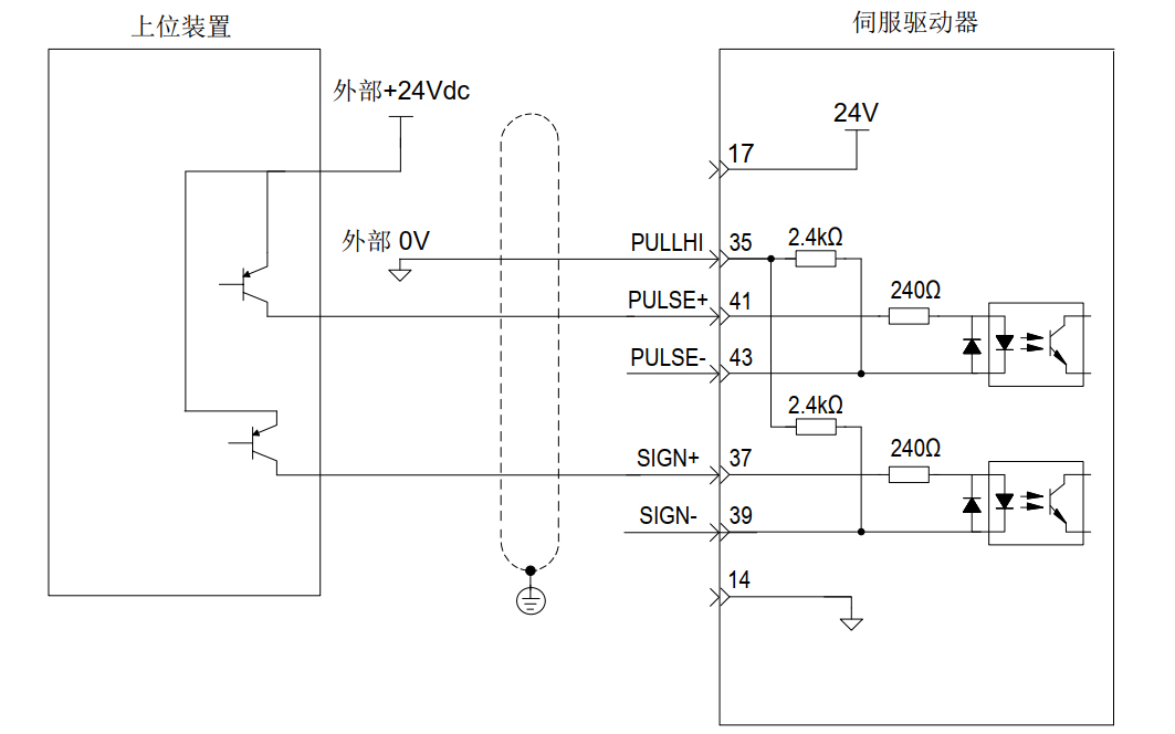
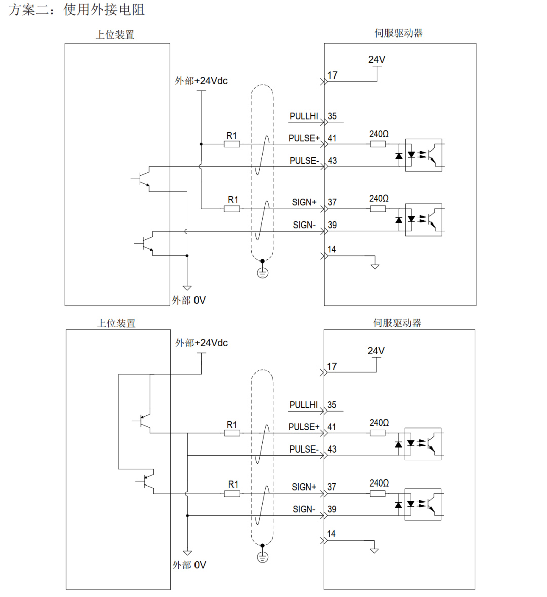
也可采用外接电阻的接线方案,当脉冲和方向信号为5V时,不需要接电阻,当脉冲和方向信号为24V,R1和R2必须接2KΩ左右的电阻,否则会造成驱动器损坏。
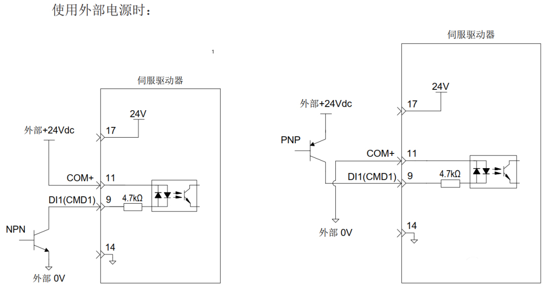
接好位置输入信号线,接下来就是连接数字输入/输出端子线。


编码器分频输出电路:当需要将伺服编码器信号连接到PLC进行闭环控制时,不可能直接从电机上分线,所以驱动器提供了编码器分频输出。

编码器分频输出电路通过差分驱动器输出差分信号,上位机请使用差分或光耦接收电路接收,最大电流为20ma。

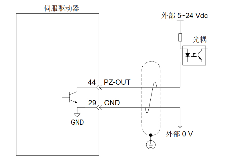
编码器Z相分频输出电路可通过集电极开路信号。通常,为上级装置构成位置控制系统时,提供反馈信号。在上级装置侧,请使用光电耦合器电路、继电器电路或总线接收器电路接收。
看到这里接线应该就没问题了,剩下的就是设置参数和编写发脉冲主程序了
相关链接:汇川IS620P伺服驱动器与H3U系列PLC之间使用CANLink通讯时的故障处理